Chinese | English
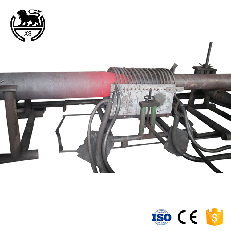
Mechanical pipe expanding machine
Mechanical parameters
|
Type |
3”—12” |
8”—24” |
16”—30” |
20”—36” |
30”—48” |
|
Pipe wall thickness |
Sch80 |
||||
|
Maximum pressure |
31.5MPa |
||||
|
Pressure of work |
25 MPa |
||||
|
Working speed |
0—1000mm/min |
||||
|
Fast speed back |
1500—2000mm/min |
||||
|
Inner diameter of hydraulic |
180*2 |
250mm*2 |
360mm*2 |
320mm*4 |
360mm*4 |
|
Hydraulic cylinder stroke |
6500mm |
6500mm |
6500mm |
6500mm |
6500mm |
|
Hydraulic cylinder thrust |
60T*2 |
120T*2 |
250T*2 |
200T*2 |
250T*4 |
|
The motor power |
22.5kw |
46kw |
48.5kw |
75kw |
100kw |
|
Intermediate Frequency power Supply required |
250kwa |
400kwa |
600kwa |
800kwa |
1000kwa |
Mechanical video
Equipment details
Mechanical pipe expanding machine
1. Mechanical diameter expanding machine equipment: mechanical diameter expanding machine is composed of rotating idler device, lifting cone roller table, driving tie rod sleeve supporting roller, length measuring roller, clamping trolley, diameter expanding head, tie rod, tie rod sleeve, diameter expanding machine hydraulic cylinder and rack.The purpose of the mechanical expanding machine is to enlarge the pipe with expanding head step by step to obtain the roundness, straightness and dimensional accuracy required by the standard technology.
Ii. Process: the rinsed pipe is sent to the rotary idler device on the center line of the enlarging machine.Using this rotating idler device, combined with the camera system, the tube weld is precisely rotated to the 12 o 'clock position to ensure that the weld can enter the groove of the upper sector of the tool during subsequent diameter enlargement.The lifting cone roller way lifts the pipe to the center line of the reaming machine and the position is controlled by the displacement sensor in the lifting hydraulic cylinder.The clamping trolley moves forward and is controlled by a metal detector to detect the end of the tube and to secure it. At the same time, a signal is sent to start the feeding roller of the clamping trolley. The position is controlled by an encoder.The pipe length is combined with the reaming head to automatically calculate the optimal reaming steps.The clamp jaws can be rotated to avoid damaging the tube wall.During the advance, the height of the clamp can be adjusted to compensate for the pipe straightening deviation and optimize the straightening effect of the reamer.
- About us ABOUT US Company culture Production ability Service Process Service philosophy
- Device list ELBOW MACHINE PIPE BENDING MACHINE EXPANDING MACHIEN TEE MACHINE BEVELING MACHINE PRESS MACHINE MOULDS
- Video Center ELBOW MACHINE PIPE BENDING MACHINE PIPE EXPANDING MACHINE TEE MACHINE VIDEO BEVELING MACHINE PRESS MACHINE MOULDS VIDEO
- News Center Company news Business news
- Contact us Contact us Web site map
-
